SELECTED WORK / PROJECT 002

Solaris Mk2Project Zenith's SRAD hybrid engine

Engine component design for the rocket that earned Monash HPR second place at IREC 2025.

Mechanical designSystems engineeringCAD & drawingsManufactureFlight integration
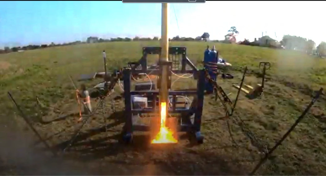
Solaris Mk2 firing on a vertical ground-test stand during the Zenith propulsion validation campaign
SOLARIS MK2 / STATIC-FIRE CAMPAIGNGROUND VALIDATION FOR PROJECT ZENITH
MY ROLE
Engine component design
TEAM
Monash High Powered Rocketry
MISSION
Project Zenith · IREC 2025
DEVELOPMENT
2023–2025

01 / THE CHALLENGE

From component
to competition.

Solaris Mk2 powered Project Zenith, Monash HPR's 10,000 ft Hybrid SRAD entry at IREC 2025.

  • My work focused on engine component design within the propulsion team.
  • The engine paired nitrous oxide with a paraffin/ABS fuel grain inside an aluminium chamber.
  • Mk2 preceded Solaris Mk3, linking my work on flight hardware with the later composite chamber project.
2nd

IREC 2025 category place
10,000 ft Hybrid SRAD

10,000 ft

Zenith altitude target

~10 kN·s

Reported nominal engine impulse

02 / SYSTEMS ENGINEERING

A mission becomes
hardware.

  • The 10,000 ft mission target set the engine performance requirements.
  • Component decisions balanced pressure, temperature, mass, access and workshop capability.
  • The project progressed from concept selection through design review, testing and flight validation.

FROM SPECIFICATION TO DESIGN DECISION

Criteria that shaped the parts

  • Performance: Set a 2.7 kN peak-thrust criterion and a 10,000 N·s total-impulse target.
  • Operating conditions: Maintain engine performance across the 15–35°C operating range.
  • Load transfer: Carry chamber thrust through the interface into the tank and vehicle structure.
  • Assembly: Use adjustable threaded interfaces to preload the chamber internals and engage the seals.
  • Integration: Centre the chamber in the airframe while limiting assembly complexity.
  • Manufacturing: Select stock sizes and processes that the team could source and machine.

These are design criteria, distinct from the recorded test results.

03 / DESIGN & ANALYSIS

One engine.
Connected parts.

CAD connected the component geometry to the engine's pressure, thermal and structural interfaces.

Engine architecture

Packaging around Zenith

  • A six-inch oxidiser tank supported the mission without an excessively long four-inch tank.
  • The structural interface connected the larger tank to the four-inch chamber.
  • Space around the interface accommodated valves, fittings and the internal fill line.

04 / ENGINE COMPONENTS

Designing the
details.

  • My component work sat within the complete engine assembly.
  • The following views show how the team’s documented design addressed fit, thermal protection and load transfer.

COMPONENT 01

Chamber wall & retention

  • The aluminium 6061-T6 chamber contained the pressure around the fuel and thermal protection stack.
  • Threaded closures provided internal compression and allowed quick engine cycling.
  • The aft centring ring supported the smaller chamber within Zenith’s six-inch airframe.
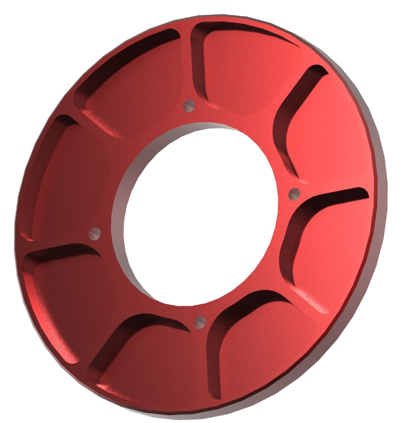
Chamber and centring ring CAD

COMPONENT 02

Fuel grain & liner

  • A printed ABS gyroid supported the otherwise brittle paraffin fuel.
  • The cylindrical port simplified casting and suited the engine’s blowdown architecture.
  • Available printer height limited grain length, while a PVC liner protected the chamber wall.
Fuel grain development drawing

COMPONENT 03

Pre- & post-combustion chambers

  • The short pre-chamber shielded the forward closure and transitioned flow from the injector.
  • The post-chamber provided space for mixing before the nozzle.
  • The later design used a post-chamber length-to-diameter ratio of 1.5.
Pre-chamber development drawing

COMPONENT 04

Nozzle & thermal interfaces

  • The later design used graphite for both the throat and diverging section.
  • A phenolic sleeve separated the conductive graphite from the adjacent aluminium wall.
  • The retaining ring connected nozzle retention with the aft support structure.
Nozzle retaining ring drawing

COMPONENT 05

Structural interface & centring

  • The ring and adapter transferred thrust between the chamber, tank and rocket structure.
  • Tube stock reduced material waste compared with machining the whole interface from billet.
  • Large windows preserved access to the valves and fittings inside the interface.
View the aft centring ring
Structural interface CAD

05 / DESIGN EVOLUTION

Review.
Build. Refine.

Later Mk2 configuration

CONCEPT SELECTION → DESIGN REVIEW → TESTING

Changes driven by the mission and the hardware

  • Preliminary design compared a tube-and-billet interface with a single-billet alternative.
  • Detailed design defined the ring-and-adapter load path and its initial analysis.
  • The later engine configuration progressed through static-fire testing and competition flight.
  • Tank: A six-inch tank replaced the original four-inch arrangement to limit engine length.
  • Actuation: Nitrous tap-off pilot-valve actuation replaced the earlier offboard CO₂ system.
  • Nozzle: Excessive erosion of the phenolic diverging section prompted the switch to an all-graphite nozzle.
  • Interface: The ring design balanced load transfer, material use and access to internal components.

06 / MANUFACTURE & INTEGRATION

Designed for
the workshop.

  • Turning and CNC machining produced the chamber and structural interface parts.
  • Printed ABS supported the cast paraffin grain within the available printer build height.
  • Threaded closures and accessible windows supported assembly, inspection and engine servicing.
Engine assembly photograph
Tank and active-vent hydrotest setup

07 / TESTING & FLIGHT

Evidence on
the test stand.

  • Static fires recorded thrust and pressure across successive engine configurations.
  • The July 2024 test delivered 10,089 N·s, close to the 10,000 N·s target.
  • Hydrotests checked the cold nitrous-storage and transport components at 95 bar.
  1. 2023

    First hot-fire

    Mk2 reached its first hot-fire in September, three months after the initial concept.

  2. 2024

    Ground and flight validation

    Static tests and two Zenith validation flights built evidence for the competition configuration.

  3. 2025

    IREC competition

    Zenith flew with Mk2 and earned second place in the 10,000 ft Hybrid SRAD category.

July static-fire thrust curve

TESTS ALSO EXPOSED LIMITS

Performance and
thermal endurance.

  • Changes in fill and ambient conditions altered peak thrust and burn duration.
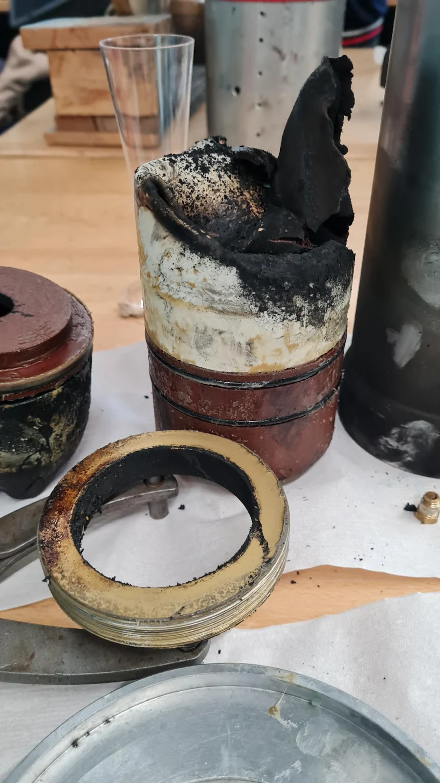
  • An overfilled May test extended the burn and damaged both the liner and chamber.
  • Inspection helped distinguish nominal performance from the limits revealed by off-nominal tests.
View the liner inspection photograph

08 / REFLECTION

The lessons
I take forward.

  • Working on Mk2 connected my component design decisions to a complete flight system.
  • The project showed how requirements, manufacturing limits and test evidence shape each other.
01

Design the interfaces together

Chamber retention, sealing, centring and access need to work as one assembly.

02

Let manufacturing inform the geometry

Stock availability, printer height and machining access directly affected the design choices.

03

Use tests to understand the limits

Thrust traces and post-test inspection exposed behaviour that nominal calculations alone could not show.

JERRY SUN / ENGINEERING PORTFOLIO

Back to selected work