SELECTED WORK / PROJECT 003

PenguinPiAutonomous shopping robot

Connecting localisation, computer vision and motion control to turn a shopping list into robot actions.

RoboticsComputer visionSLAMPath planningFeedback control
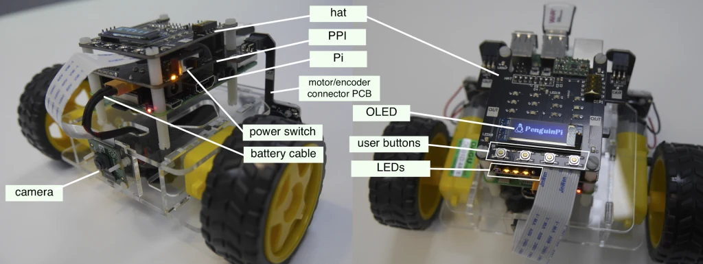
Annotated PenguinPi robot views showing its camera, drive wheels, Raspberry Pi and control electronics
PENGUINPI / DIFFERENTIAL-DRIVE PLATFORMPLATFORM PHOTOGRAPH
MY ROLE
Robotics software & integration
PLATFORM
PenguinPi mobile robot
CONTEXT
Autonomous robotics project
FOCUS
Localisation, perception & navigation

01 / THE CHALLENGE

See the world.
Move through it.

Build a mobile robot that finds grocery targets and navigates around obstacles in a small arena.

  • I worked on a team robotics project connecting sensing, mapping, planning and control.
  • The PenguinPi platform combined a camera, differential-drive wheels and a Python control interface.
  • The project progressed from robot access and calibration to integrated autonomous target visits.
3

Core milestone implementations
SLAM · Vision · Navigation

8

Grocery object categories

5

Targets in the shopping task

Milestone scope and task specifications.

02 / SYSTEMS ENGINEERING

A shared map.
A shared frame.

  • Wheel motion predicted robot pose, while ArUco observations corrected the localisation estimate.
  • Object detections became world coordinates using camera calibration and the corresponding robot pose.
  • A shared map connected perception to obstacle-aware planning and waypoint control.
System architecture · Implementation overview

DESIGNING TO THE TASK

Requirements that shaped the software

  • Arena: Operate within the specified 2.4 × 2.4 m environment.
  • Localisation: Use ten ArUco landmarks to support mapping and robot pose estimation.
  • Perception: Recognise eight grocery categories and estimate their positions.
  • Navigation: Generate waypoints from the map and avoid marker blocks and non-target objects.
  • Target visit: Stop the entire robot within 0.25 m of a target for approximately two seconds.
  • Integration: Keep images, robot poses, object estimates and motion commands consistent.

These are task criteria; the implementation uses a three-second target dwell.

03 / MILESTONE PROGRESSION

Build the modules.
Connect the behaviours.

The initial checkpoint established robot communication, keyboard control and image capture.

M1 / CALIBRATION & SLAM

Locate the robot

  • Calibrated camera intrinsics, distortion, wheel scale and wheel separation.
  • Implemented differential-drive prediction and EKF landmark updates.
  • Added parameter sweeps and map-alignment tools for assessing localisation.

M2 / COMPUTER VISION

Map the groceries

  • Prepared object-detection training workflows and background augmentation.
  • Estimated object range and bearing from bounding boxes and physical dimensions.
  • Merged repeated observations into object positions using DBSCAN clustering.

M3 / AUTONOMOUS NAVIGATION

Act on the map

  • Implemented Theta* path planning with robot-footprint clearance checks.
  • Used feedback control to follow waypoints and approach targets.
  • Coordinated scanning, exploration, target visits and retreat through a state machine.

Initial implementations cover M1–M3; later checkpoints and the final demonstration remain outlined.

04 / LOCALISATION

Calibration before
confidence.

  • Camera calibration connected image measurements to real geometry.
  • The wheel model converted left and right wheel speeds into robot translation and rotation.
  • EKF prediction propagated motion uncertainty before landmark observations updated the state.
  • Evaluation tools compared landmark maps after coordinate-frame alignment.
Camera calibration rig · Example
SLAM interface · Example

05 / PERCEPTION & OBJECT MAPPING

From pixels
to positions.

  • YOLO detections supplied object labels and image bounding boxes.
  • Known object height and focal length provided a range estimate.
  • Robot pose and the camera offset transformed detections into world coordinates.
  • Geometry filters and clustering reduced duplicate or implausible position estimates.

TRAINING & GENERALISATION

Vary the scene,
keep the label.

  • Background randomisation expanded the variety of training scenes.
  • The generator created YOLO-format annotations while checking object overlap.
  • Training notebooks supported detector development alongside the geometric mapping pipeline.
Target object categories
Integrated vision and SLAM interface · Example
Bounding-box detection · Example

07 / VALIDATION & INTEGRATION

Check each layer.
Then the system.

  • Calibration parameters, reference maps and evaluation scripts support implementation checks.
  • Map alignment supported comparison between estimated landmarks and their reference coordinates.
  • Integrated navigation depended on perception, localisation and control working in the same coordinate frame.
  1. 01

    Calibrate and replay

    Use calibration records and saved observations to assess the motion and landmark models.

  2. 02

    Evaluate the map

    Compare aligned landmark and object estimates with the reference arena.

  3. 03

    Integrate the behaviour

    Connect scan decisions, planning, waypoint control and target visits in the autonomous loop.

DESIGN CHOICES FOR INTEGRATION

Keep observations
and actions consistent.

  • Image capture retained the corresponding robot pose for object mapping.
  • Stationary observations reduced motion blur before detection.
  • Repeated object observations were clustered before planning target approaches.
  • Pause, finish and shutdown paths provided explicit control over robot motion.

08 / REFLECTION

The lessons
I take forward.

  • This project connected robotics algorithms to the practical details of sensing, timing and motion.
  • It reinforced the value of clear interfaces between software modules.
01

Calibration affects every downstream decision

Small geometry errors can propagate from localisation into object positions and planned paths.

02

Plan for a robot with a footprint

A collision-free centreline still needs enough clearance for the physical robot.

03

Make behaviour visible

Explicit states and visual feedback help explain why the robot scans, moves, stops or retries.

JERRY SUN / ENGINEERING PORTFOLIO

Back to selected work